Network Segmentation with AWS Transit Gateway
Navigating the complex terrains of modern digital networking often unveils a host of challenges, particularly with the escalating demands for enhanced efficiency and fortified security. AWS Transit Gateway emerges as a beacon of simplification amidst this complexity, offering a streamlined architecture and the boon of segmentation to bolster both organisational scalability and security. Through my engagements, I frequently encounter queries about network segmentation using AWS Transit Gateway, revealing a common thread of uncertainty among customers when it comes to the nuances of association, propagation, and creating different routing tables. With this backdrop, I am propelled to demystify these aspects and offer a tangible roadmap to navigate them. In this blog post, we will delve into the heart of Transit Gateway segmentation, unraveling its practical implementation through the AWS console with a hands-on example. This expedition aims not only to elucidate the theoretical underpinnings but to provide a practical walkthrough to aid in clarifying the often murky waters surrounding association, propagation, and the creation of different routing tables in AWS Transit Gateway.
The following topics will be covered in our discussion today:
What is AWS Transit Gateway (TGW)
TGW Route Tables
VPC Route Tables
TGW Attachments
How Segmentation works: Association VS Propagation
Intro to Architecture and Topology
Segmentation: Hub&Spoke
Segmentation: Inspection
Segmentation: Centralised Egress
How to Segment your Environment with AWS Transit Gateway
Conclusions
What is the AWS Transit Gateway (TGW)
AWS Transit Gateway acts as a regional virtual router, allowing you to interconnect your Virtual Private Clouds (VPCs) and on-premises networks through a single gateway. It simplifies your network architecture, scales routing across VPCs, VPNs, and on-premises networks, and offers a centralised model for routing and security. Transit Gateway’s route tables and routing domains enable segmentation, where each domain adheres to a set of routing policies, facilitating efficient traffic management, enhanced security, and simplified multi-account, multi-VPC connectivity. Through route propagation and BGP (Border Gateway Protocol) routing, Transit Gateway dynamically learns and adapts to network changes, reducing operational overhead while maintaining a robust, scalable network infrastructure.
TGW Route Tables
Continuing from the centralised routing model of AWS Transit Gateway, its route tables play a pivotal role in orchestrating traffic flow across your network. A route table contains a set of rules, called routes, that are used to determine where network traffic is directed. Each Transit Gateway can have multiple route tables, allowing for the segmentation of networks akin to Virtual Routing and Forwarding (VRF) technology, which enables a router to maintain multiple routing tables simultaneously for network segmentation. As traffic exits a VPC, the Transit Gateway references the associated route table to determine the destination, ensuring traffic is directed to the correct segment, be it another VPC, a VPN connection, or a Direct Connect gateway, emulating the structured, segmented routing framework provided by VRF within AWS environments.
Additionally, we can’t avoid talking about the Default Route Table, yes there is one! Upon deploying a Transit Gateway, a default route table is automatically created. When you attach a VPC, VPN, or Direct Connect to the Transit Gateway, entries are auto-populated in this default route table facilitating connectivity between the attached resources without additional configuration. However, while convenient, this setup permits communication between all attached resources without segmentation. For more controlled, segmented traffic flow, additional route tables and configurations would be necessary, else the default behaviour allows broad connectivity across all attachments, potentially conflicting with desired network segmentation and security policies.
VPC Route Tables
For precise traffic routing, it’s imperative to configure the VPC route table alongside the Transit Gateway route tables. Within the VPC route table, entries must be made directing traffic to the Transit Gateway attachment for specified destinations. This ensures that traffic destined for particular network segments is forwarded to the Transit Gateway, which then consults its own route tables to route the traffic accordingly. In a VPC, a route table contains a set of rules that dictate how traffic is forwarded to various destinations, acting as a roadmap for navigating traffic through the network infrastructure, thus facilitating accurate and efficient routing to the Transit Gateway and beyond. To leverage the segmentation capabilities offered by AWS Transit Gateway (TGW), it’s crucial to have both the Transit Gateway route tables and the VPC route tables correctly configured. This dual-level routing setup forms a structured pathway, guiding traffic securely and efficiently across the various segments of your network infrastructure.
TGW Attachments
In order to fully understand how TGW works, we need to start from the concept of “Attachment”. An attachment in AWS Transit Gateway serves as the bridge for traffic flow between the gateway and other network entities such as VPCs, VPN connections, Direct Connect gateways, and more. Here’s a list of the types of attachments you can have with AWS Transit Gateway:
1. VPC Attachments:
- Attaching a VPC to a Transit Gateway entails specifying a subnet from each Availability Zone for the gateway to route traffic through.
- Within the chosen VPC subnets, AWS Transit Gateway deploys an elastic network interface to handle traffic routing to and from the Transit Gateway.
2. VPN Attachments:
- A VPN attachment enables the association of a VPN connection with the Transit Gateway, making it possible to route traffic between your on-premises network and the AWS cloud securely via a VPN tunnel.
3. Direct Connect Gateway Attachments:
- When a Direct Connect gateway is attached, a private linkage between your on-premises network and AWS is established, allowing traffic routing over a dedicated network connection (Direct Connect).
4. Peering Connections:
- Peering comes into play when two Transit Gateways are interconnected, facilitating the routing of traffic between them, which is especially useful for inter-region traffic routing within AWS.
5. Transit Gateway Connect Attachments:
- This is a logical attachment type that allows your TGW to establish a connection with a 3rd party SD-WAN Appliance. It supports standard protocols like Generic Routing Encapsulation (GRE) and Border Gateway Protocol (BGP) over the Connect attachment, providing a streamlined way to manage routing protocols.
Each attachment type is instrumental in defining how traffic is navigated and managed through the AWS Transit Gateway, contributing to a robust, scalable, and secure network architecture adaptable to various network setups and configurations.
How Segmentation works: Association VS Propagation
Let’s talk about Association now that we discussed the concepts for ‘Attachments”. Association in the context of AWS Transit Gateway refers to the linking of a route table to a particular attachment, be it a VPC, VPN, Direct Connect gateway, or peering connection. This association directs how traffic is routed from the attachment through the Transit Gateway.
1. Route Table Association:
- By default, the attachment is associated with the default route table of the Transit Gateway unless specified otherwise.
- You can also create Custom Route Tables and associate them to the attachments.
2. Traffic Routing:
- Once an attachment is associated with a route table, the routing rules defined in that route table govern the traffic flow from the attachment.
- The route table contains entries that tell the Transit Gateway how to route traffic from the associated attachment to other attachments or network segments.
3. Customisation and Segmentation:
- You can create multiple route tables within a Transit Gateway to achieve network segmentation and more granular control over traffic routing.
- By associating different attachments with different route tables, you can control which network segments can communicate with each other.
4. Route Propagation:
- Besides manual entry, route tables can automatically learn routes from the attachments through a feature called route propagation.
- When an attachment is associated with a route table and route propagation is enabled, the routes from the attachment are automatically propagated to the route table, simplifying route management.
5. Overriding Defaults:
- You can override the default association by explicitly associating an attachment with a different route table.
- This allows for more sophisticated routing configurations and network architectures.
Association is a fundamental aspect of managing traffic flow through AWS Transit Gateway. By associating route tables with attachments, you dictate the paths that traffic can take through the Transit Gateway, enabling organised, efficient, and secure network communication.
Propagation on the other hand, refers to the automatic “dissemination” of routes from an attachment to the Transit Gateway’s route table. This feature alleviates the need for manual route entry, enhancing route management efficiency. Here’s an in-depth look at propagation:
1. Route Propagation Mechanism:
- When an attachment is associated with a route table and route propagation is enabled, the Transit Gateway automatically populates the route table with routes from the attachment, facilitating seamless connectivity without manual intervention.
2. Propagation Source:
- The source of propagation can be a VPC, VPN, or Direct Connect gateway attachment, each having its own set of routes that can be propagated to the Transit Gateway’s route table.
3. Route Learning:
- AWS Transit Gateway learns the routes from the attachment and populates them in the specified route table, ensuring that the routing information is up-to-date and accurate.
4. Traffic Routing:
- Post propagation, the Transit Gateway uses the learned routes to make informed routing decisions, directing traffic to the appropriate destinations based on the most current routing information.
5. Network Scalability and Management:
- Propagation fosters network scalability and simplifies routing management, especially in dynamic or large-scale network environments where manual route entry and updates would be impractical.
6. Route Overlap Handling:
- In instances where there’s a route overlap, the Transit Gateway adheres to specific route precedence rules to determine which route to use for traffic routing. In the case of multiple routes for the same destination, the route selection follows the “longest prefix match” rule. This means that the route with the most specific (i.e., longest) prefix is chosen to route the traffic. The longest prefix match rule ensures that the most precise routing path is selected when there are multiple potential routes.
7. Propagation Control:
- You have the control to enable or disable route propagation for each attachment and route table association, allowing for fine-grained control over which routes are propagated and used for routing decisions.
8. Multi-Route Table Propagation:
- It’s possible to propagate routes from an attachment to multiple route tables, further extending the flexibility and control over traffic routing within your network infrastructure.
Propagation is a critical feature that augments the routing capabilities of AWS Transit Gateway, providing a mechanism for automatic route dissemination from attachments to the Transit Gateway’s route tables.
Intro to Architecture Topology
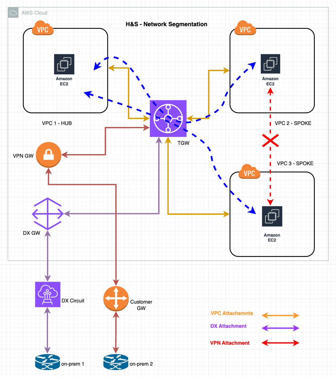
After dissecting each element in our previous discussions, we’re now equipped to grasp this comprehensive diagram. Recognize the pieces? It’s more than just understanding; it’s time to dive deep in and get hands-on. Let’s do it!
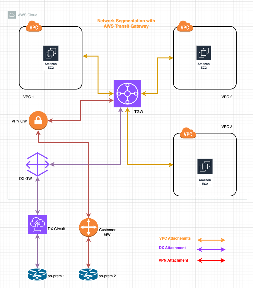
The diagram above provides a comprehensive visualisation of a network segmentation architecture using a Transit Gateway at its core. Let’s go through the specifics:
1. Central Transit Gateway: Positioned centrally, the Transit Gateway serves as the primary hub, streamlining network traffic and ensuring efficient routing between various segments.
2. VPC Attachments: There are three distinct Virtual Private Clouds (VPCs) connected to the Transit Gateway. Each VPC, houses its own set of EC2 instances. This structure allows for isolated workloads and environments while still benefitting from the centralised routing offered by the Transit Gateway.
3. Direct Connect (DX) and VPN Attachments: In addition to the VPCs, the Transit Gateway also has attachments for Direct Connect (DX) and VPN. The DX provides a dedicated network connection from on-premises data centers to the cloud, ensuring low-latency and high-throughput communication. The VPN attachment, on the other hand, offers a secure and encrypted connection over the internet.
4. On-Premises Connectivity: At the base of the diagram, we see the on-premises routers. It has dual connectivity options - one via the Direct Connect (DX) and the other through VPN. This dual-setup ensures redundancy, high availability, and the flexibility.
In essence, this Transit Gateway architecture efficiently segments the network, ensuring both isolation and streamlined connectivity. We will now go through most common patterns.
Segmentation: Hub&Spoke
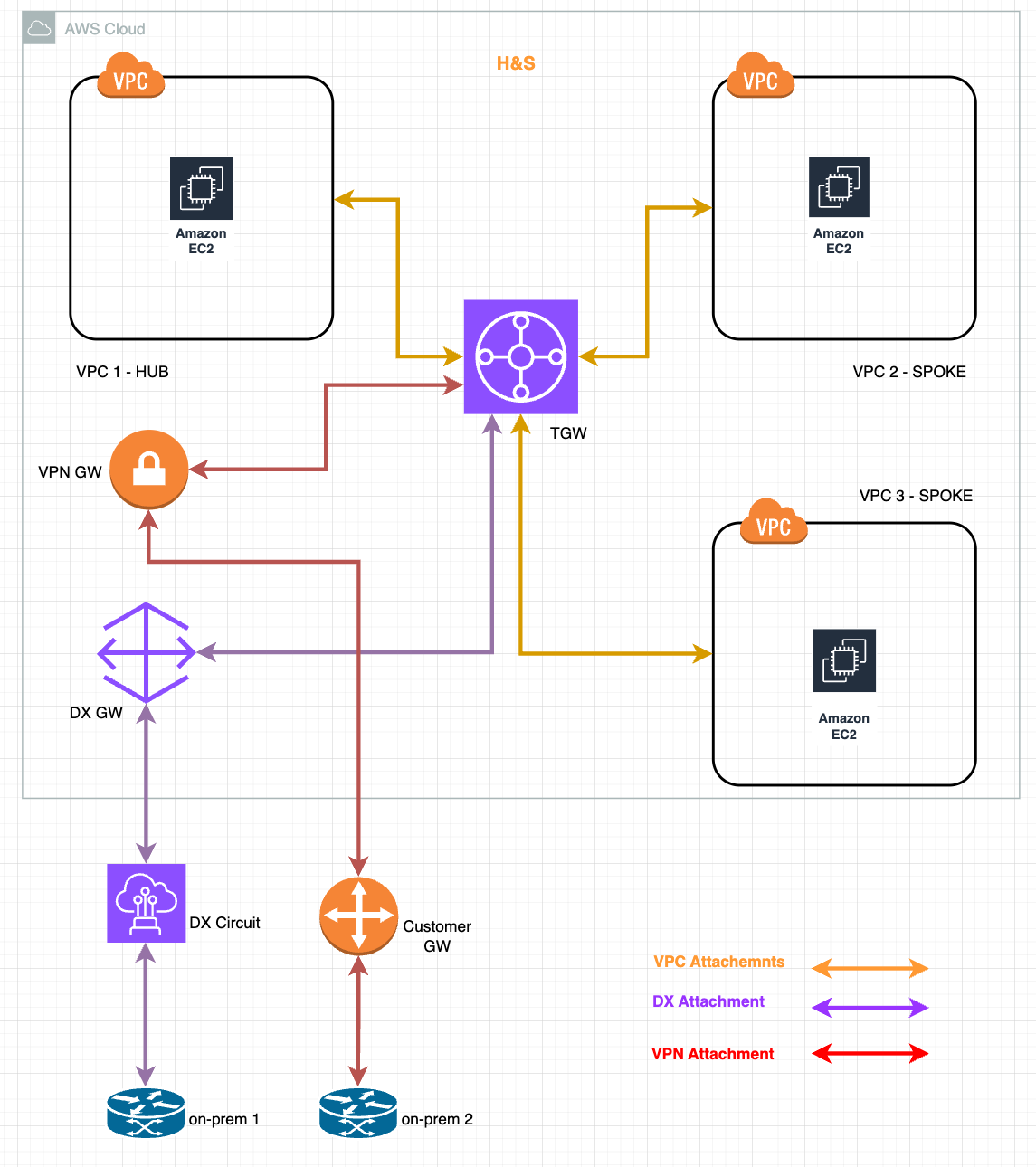
The hub-and-spoke model above is a foundational design pattern in network architecture, particularly prevalent in cloud environments.
Hub: This central unit provides shared services which can be consumed by all the spokes. It serves as the primary gateway and central point of connectivity to all the other networks. The hub has the capability to communicate with every spoke and the on-premises environment.
Spokes: These are the individual networks or segments that connect to the hub. Each spoke can access services in the hub and can communicate with the on-premises setup. However, in this model, spokes are isolated from each other, ensuring that direct communication between spokes is restricted.
Benefits of the Hub&Spoke Architecture:
1. Isolation: By preventing direct communication between spokes, sensitive data and applications are shielded from unauthorised access, enhancing security.
2. Centralised Management: The hub acts as a singular control point, simplifying network management, monitoring, and policy enforcement.
3. Scalability: New spokes can be seamlessly added without reconfiguring the entire network, making the architecture highly scalable.
4. Optimised Connectivity: Direct connections from the hub to each spoke ensure efficient and reliable communication paths.
5. Cost Optimisation: Centralising services in the hub can lead to better resource utilisation and reduced redundancy, resulting in cost savings.
6. Consistent Policy Enforcement: Policies can be uniformly applied at the hub level, ensuring consistency across the network.
7. Flexibility: While the spokes are isolated from each other, they can still access centralised services, offering a balance between security and flexibility.
In essence, the hub-and-spoke model offers a harmonious blend of security, efficiency, and scalability, making it a go-to choice for many network designers and architects.
Segmentation: Inspection
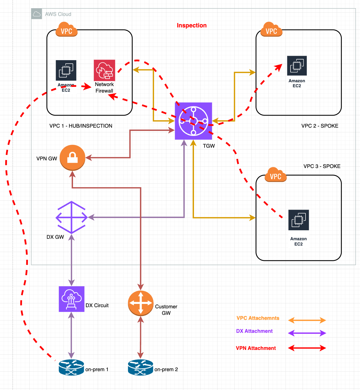
In the realm of cloud networking, especially within Cloud, securing and monitoring network traffic is paramount. Building upon the hub&spoke model, the inspection topology introduces an additional layer of security by incorporating the AWS Network Firewall in the hub, or more aptly named in this context, the “Inspection VPC”.
Inspection VPC: Positioned centrally, the Inspection VPC houses the AWS Network Firewall. Every packet of data that traverses between the spokes or from the on-premises environment to the spokes is routed through this VPC for thorough examination.
AWS Network Firewall: This managed service inspects traffic at various layers, scrutinising for malicious activities, enforcing web filtering, and applying stateful and stateless rules. Any communication between the spokes, or from on-premises to the spokes, is meticulously analysed by this firewall before being allowed to proceed.
Benefits of the Inspection Architecture:
1. Enhanced Security: With all inter-spoke and on-prem-to-spoke traffic being inspected, threats can be identified and mitigated in real-time, bolstering the security posture of the entire network.
2. Centralised Threat Intelligence: The AWS Network Firewall can be integrated with AWS’s threat intelligence feed or other third-party feeds, ensuring that the inspection is always up-to-date with the latest threat vectors.
3. Consistent Policy Enforcement: Just like the hub&spoke model, the inspection topology allows for uniform policy application, but with the added advantage of advanced traffic filtering and rule enforcement by the firewall.
4. Audit and Compliance: Traffic logs generated by the firewall provide valuable insights for auditing, forensics, and ensuring regulatory compliance.
5. Scalability with Security: While the architecture scales with the addition of new spokes or services, the security measures remain consistent and robust, thanks to the centralised inspection mechanism.
6. Cost Optimisation: By centralising traffic inspection, organisations can consolidate their security appliances, leading to cost savings in terms of both infrastructure and operational overhead.
Incorporating the AWS Network Firewall into the hub&spoke design not only retains the advantages of the foundational architecture but also elevates the network’s security, making the inspection topology a vital consideration for businesses serious about their cloud security.
Segmentation: Centralised Egress
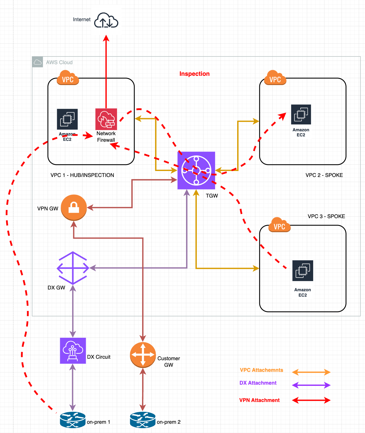
In cloud architectures, particularly with the hub-and-spoke design, one strategic approach to manage and secure outbound internet traffic is through centralised egress points. By funnelling all outbound traffic from the spokes and “optionally” from on-premises systems through the hub (for the on-prem traffic, depending on requirements, this can add complexity if implemented, depending on Cloud Providers and/or on-prem environments) – specifically through the AWS Network Firewall housed in the Inspection VPC – organisations can gain granular control and visibility over every packet destined for the internet.
Centralised Egress Point: Within the Inspection VPC, all internet-bound traffic from the spokes or from the on-premises environment is routed through this centralised point. This ensures that before any data packet leaves the network to access the broader internet, it is first scrutinised by the AWS Network Firewall.
AWS Network Firewall for Egress Traffic: As the traffic funnels through the firewall, it undergoes a detailed inspection against predefined rules and threat intelligence feeds. The firewall can block, allow, or flag suspicious traffic based on these rules, ensuring only legitimate and safe traffic is allowed egress.
Benefits of Centralised Egress Architecture:
1. Granular Traffic Control: By channeling all outbound traffic through a single point, organizations can implement detailed and nuanced egress rules, offering granular control over what can access the internet.
2. Enhanced Security: Centralised egress helps in identifying and blocking potential data exfiltration attempts, malware callbacks, or any unauthorised communication with external servers.
3. Consistency in Security Posture: With a singular egress point, security policies and rules can be uniformly applied, ensuring consistent protection against internet-based threats.
4. Cost Optimisation and Scaling: As the network grows, the centralised egress point can handle increased traffic without the need for individual egress solutions for each spoke or VPC, leading to cost savings.
5. Simplified Monitoring and Auditing: With all internet-bound traffic passing through one location, monitoring, logging, and auditing become streamlined. This centralisation aids in easier detection of anomalies and quicker incident responses.
6. Compliance Assurance: Many regulatory frameworks mandate strict control and visibility over outbound data. Centralised egress helps organizations meet such compliance requirements by offering a controlled and logged exit point for all data.
7. Reduced Attack Surface: By limiting outbound traffic to one managed point, the potential avenues for attacks or breaches are significantly reduced.
In line with cloud best practices, centralised egress through the AWS Network Firewall not only augments the security of the architecture but also streamlines management, monitoring, and compliance efforts, making it a pivotal strategy for organizations aiming for robust cloud security.
How to Segment your Environment with AWS Transit Gateway
Let’s get our hands on the keyboard now and have fun with the following lab. This guide aims to walk you through the process of setting up network segmentation for an environment consisting of three VPCs, one Direct Connect (DX) link, and one VPN connection. Here, VPC 1 will act as the central hub, while VPC 2 and VPC 3 will serve as the spokes. In our Lab we don’t have a dedicated Direct Connect and VPN so we will be focusing on segmenting only the VPC traffic. By employing the hub-and-spoke model, we ensure optimal communication paths, streamlined management, and enhanced security. Have fun!
1. VPC and Subnet Creation:
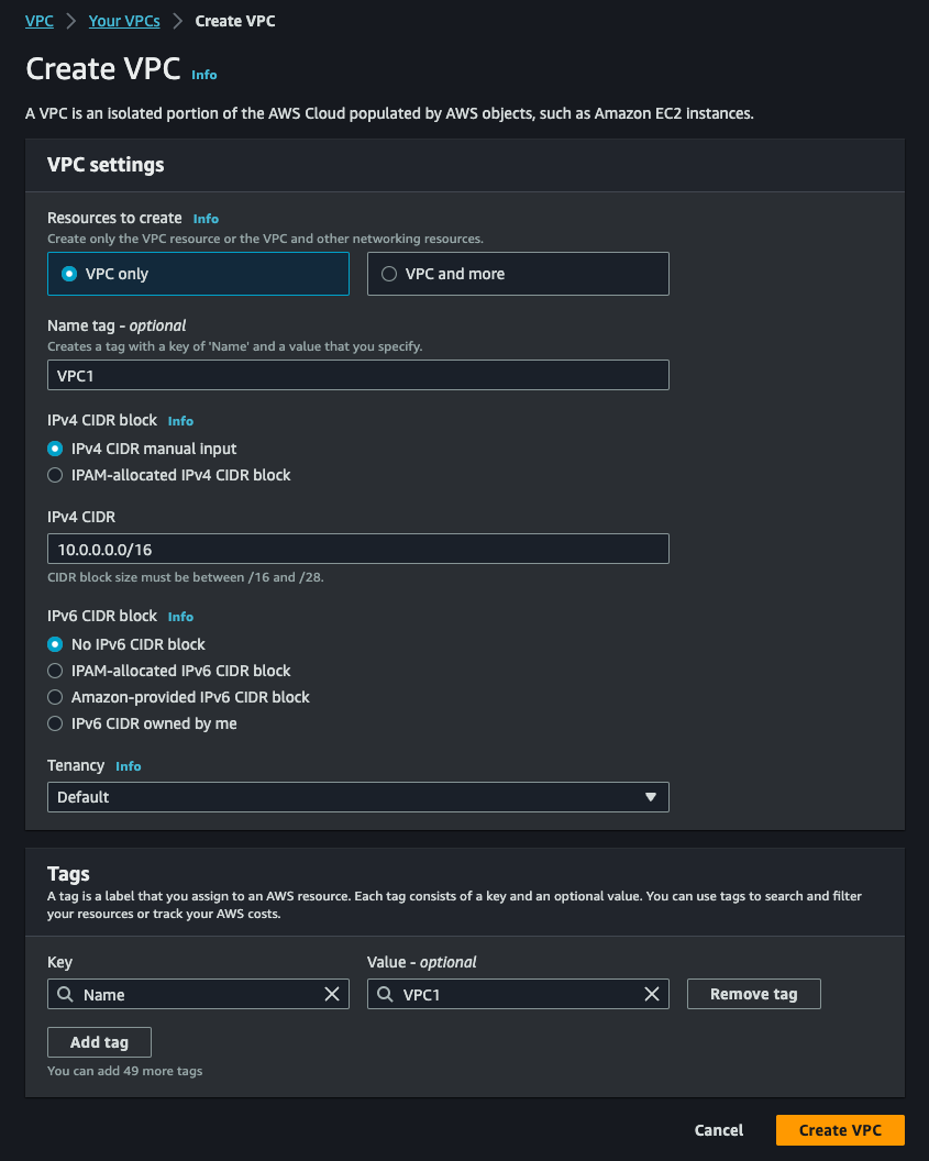
1.1. VPC 1 (Hub):
- Navigate to the VPC Dashboard.
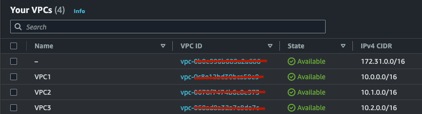
- Create VPC: CIDR block: 10.0.0.0/16
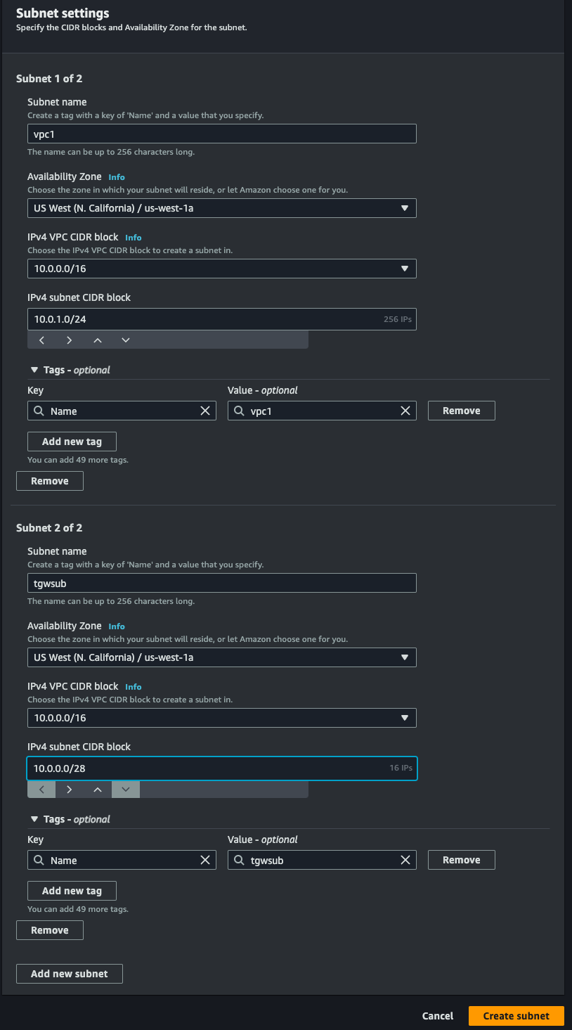
- Create Subnet within HubVPC:
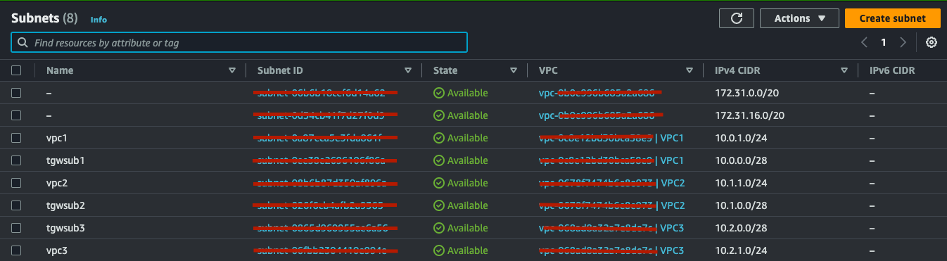
- CIDR block: 10.0.1.0/24
- Subnet TGW: 10.0.0.0/28
1.2. VPC 2 (Spoke 1):
- Create VPC: CIDR block: 10.1.0.0/16
- Create Subnet within SpokeVPC1:
- CIDR block: 10.1.1.0/24
- Subnet TGW: 10.1.0.0/28
1.3. VPC 3 (Spoke 2):
- Create VPC: CIDR block: 10.2.0.0/16
- Create Subnet within SpokeVPC2:
- CIDR block: 10.2.1.0/24
- Subnet TGW: 10.2.0.0/28
PLEASE NOTE - we are creating this lab in a single Availability Zone (AZ) which is not advised in production environments, we should alway follow resiliency best practices. For the purpose of this lab we are making things simple.
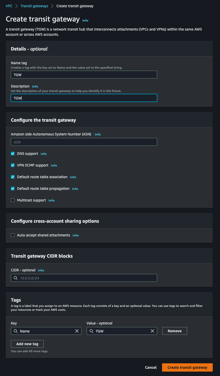
2. Transit Gateway Creation:
- Navigate to the Transit Gateway section.
- Create a new Transit Gateway.
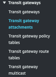
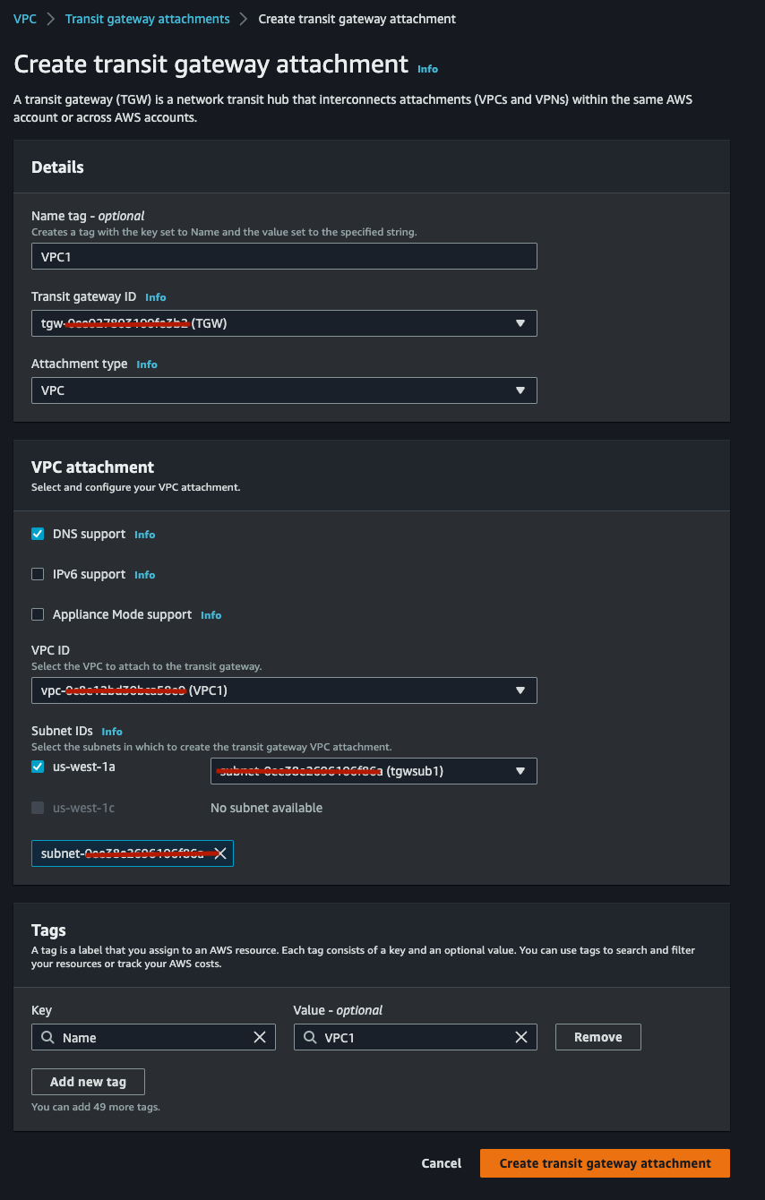
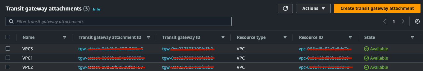
3. Transit Gateway Attachments:
- Navigate on the bottom left corner under Transit Gateway, click on “Transit Gateway Attachments”.
- Attach HubVPC (VPC1), SpokeVPC (VPC2), SpokeVPC (VPC3) repeat 3 times - (only VPCs as VPN and DX are not available in our lab). Attach the TGW to the VPC1, 2 and 3 using the /28 Subnets we created in the previous section.
4. Transit Gateway Route Tables, Associations and Propagations Creation and Configuration:
4.1. Default Route Table:
- Modify the default route table to ensure spokes don’t have routes to each other.
- Go to Transit Gateway Route Tables and click on the one with the TGW ID = to your TGW ID.
- Click on Association Tab.
- Remove all Associations one by one.
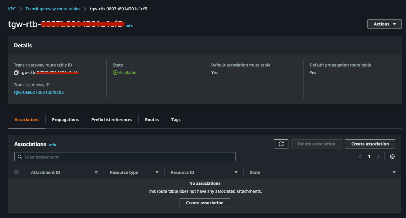
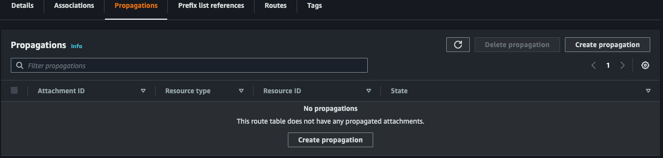
- Go now on Propagation Tab.
- Remove all Propagations.
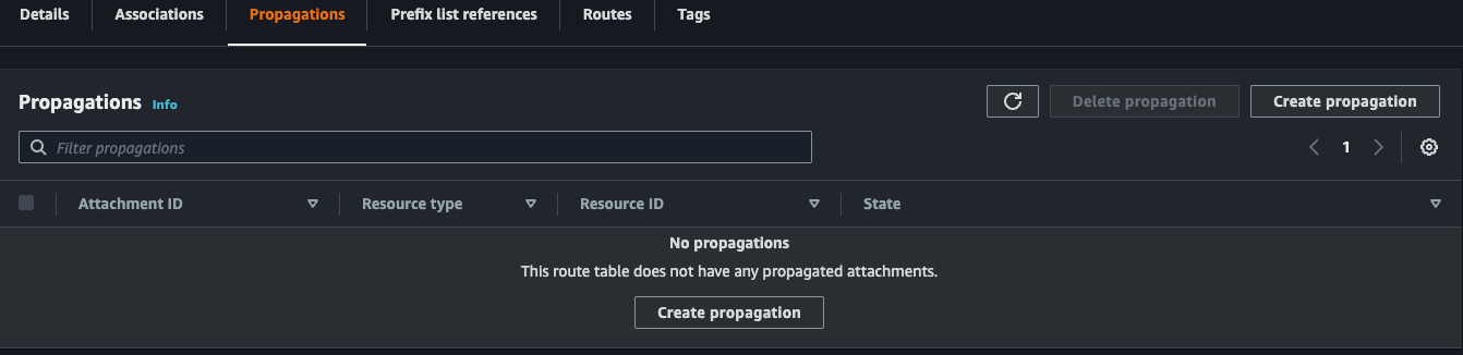
- At this point, the routes previously learned automatically, will be removed. After you deleted the Associations and Propagations, please verify you have no Routes in the Routes Tab.
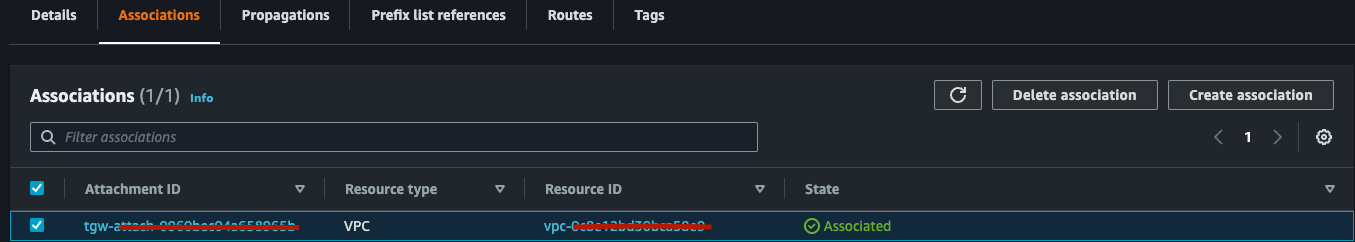
Now we need to associate the this route table to the VPC1 attachment as VPC1 is the HUB and needs to be able to communicate with all spokes and on-prem.
- Click on Associations
- Create Association
- Select the VPC1 Attachment
You should have something like this:
At this point, if things worked well, we should be able to see the Propagations Tab and the Routes Tab populated with propagations and routes to the other VPCs:
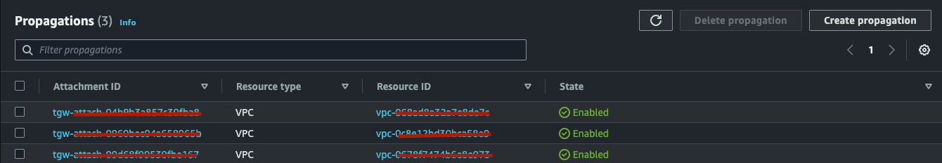
PLEASE NOTE - While propagations and routes might auto-update based on attachments and based on the fact that we modified the “Default Routing Table” (Default has enabled by default Association and Propagation for all Attachments) I’ve walked you through the manual process intentionally. The hands-on approach ensures a deeper understanding and helps the concept resonate more strongly with you. Alternatively, you could just create 2 new RTs HUB-RT and SPOKES-RT for example.
4.2. Spokes Route Table:
- Create a new route table.
- Click on Create TGW Route Table
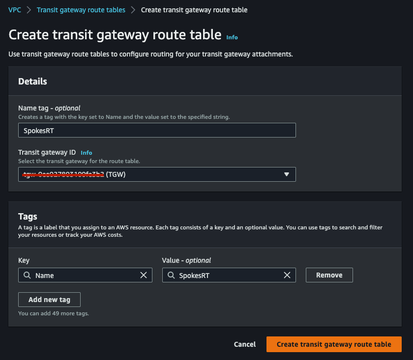
- Click on the newly created Route Table.
- Click on Associations Tab.
- Create 2 Associations, one for VPC2 and one for VPC3.
- Now click on Propagations Tab.
- Because we want to make sure Spokes only communicate with the HUB (VPC1), we want to Propagate ONLY the VPC1 Attachment.
- Click on Create Propagation.
- Select VPC1.
At this point if you done things correctly, you should see the following:
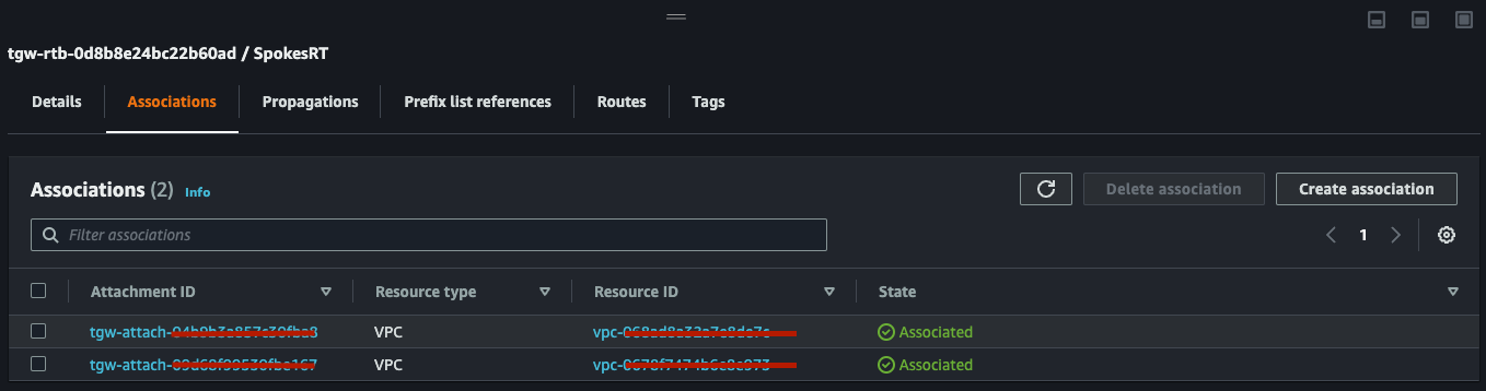
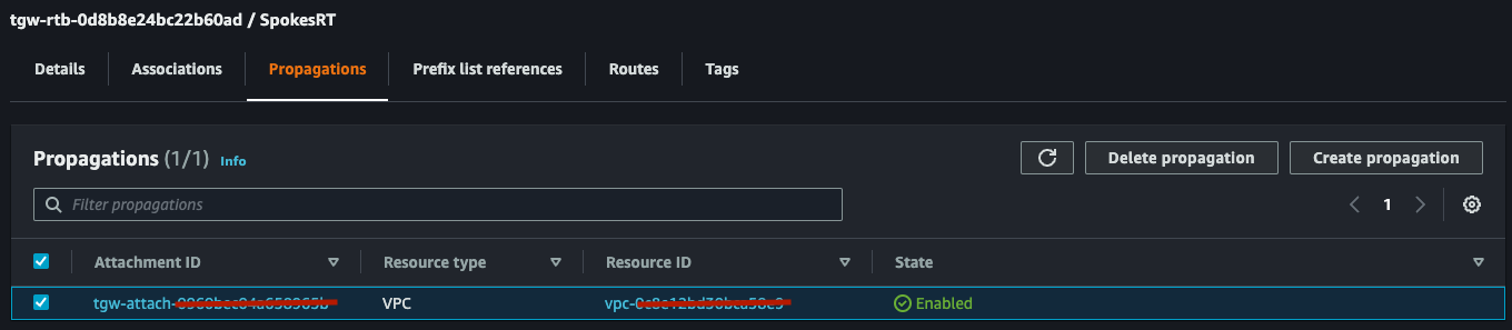
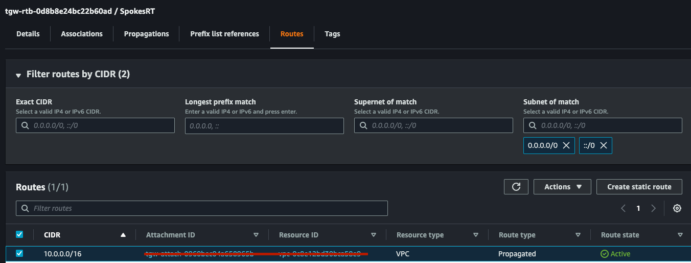
As you can see you have, 2 Associations (VPC2 and VPC3 - Spokes), 1 Propagation (only HUB VPC1) and 1 Route in the Route Tab as we only propagated HUB (VPC1) Routes into this Route Table. CongratZ! Now we need to make sure we have routing in place for the VPCs, let’s see how.
5. VPC Route Tables Creation and Configuration:
5.1. Hub VPC1 Route Table:
- Click on VPC1 HUB RT (previously automatically created during VPC creation, I changed the name of the RT by clicking on the pen/pencil next to the ”-” under the Name column).
- Click on Route Tab.
- Click on Edit Routes.
- Add Route.
- Add Destination 10.0.0.0/8 (we are summarising 10.1.0.0/16 and 10.2.0.0/16 into 10.0.0.0/8).
- As Target, select Transit Gateway, then select the one we created before.
- Click on Save Changes.
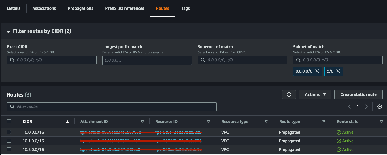
At this point you should see the following:
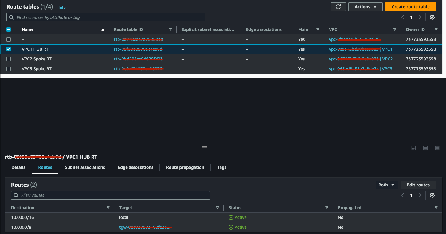
Local is the local CIDR for the VPC, 10.0.0.0/8 is the CIDR related to the Spokes.
5.2. Spoke VPC2 Route Table:
- Repeat steps at point 5.1 but add as Destination 10.0.0.0/16 as we can only communicate with the HUB.
5.3. Spoke VPC3 Route Table:
- Repeat steps at point 5.1 but add as Destination 10.0.0.0/16 as we can only communicate with the HUB.
At this point you should have for both, VPC2 and VPC3 the following:
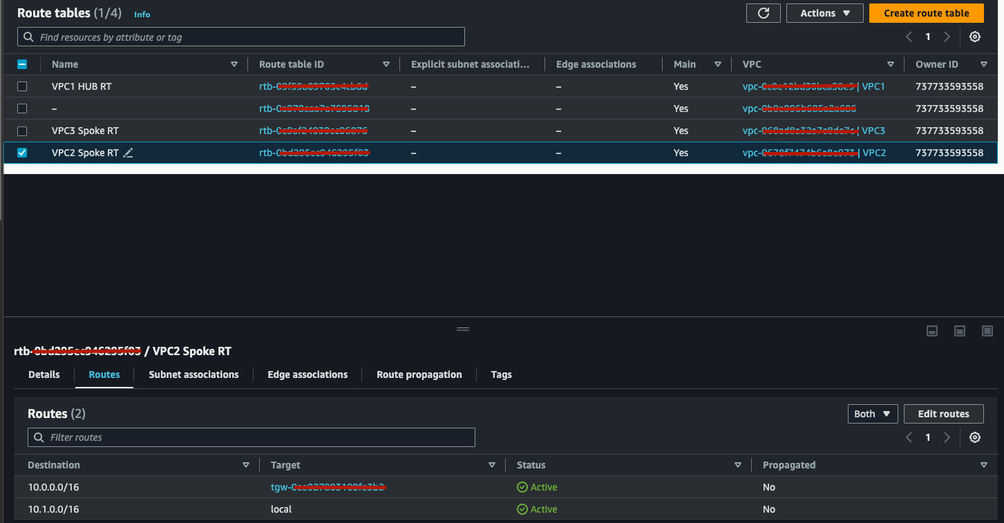
The only difference you will see, for the VPC3, you will see a different Local CIDR, 10.2.0.0/16.
At this point, if you followed perfectly, you will have achieved the following Network Segmentation:
6. Testing:
- Deploy EC2 instances in each VPC and validate communication as per the design requirements. You can use Session Manager and ICMP tests.
- Remember to create the IAM role to allow Session Manager to work and remember to deploy Session Manager as well if you don’t want to access instances via ssh.
- I won’t discuss the details of how to deploy EC2 Instances and how to configure them as this post is focused on Networking.
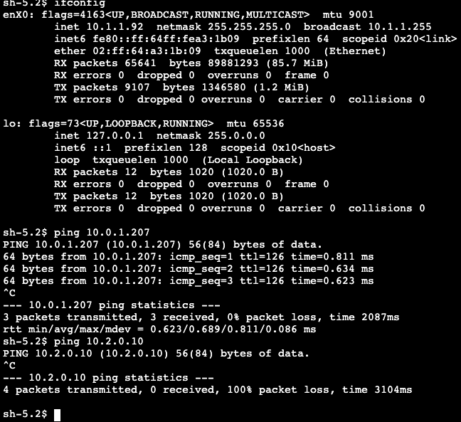
- In my environment we have:
VPC1-SRV (HUB) 10.0.1.207
VPC2-SRV (Spoke1) 10.1.1.92
VPC3-SRV (Spoke2) 10.2.0.10
ICMP Test from HUB to Spokes:
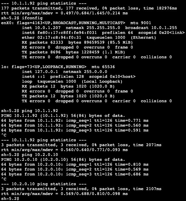
ICMP Test from Spoke1 to HUB and to Spoke2:
ICMP Test from Spoke2 to HUB and to Spoke1:
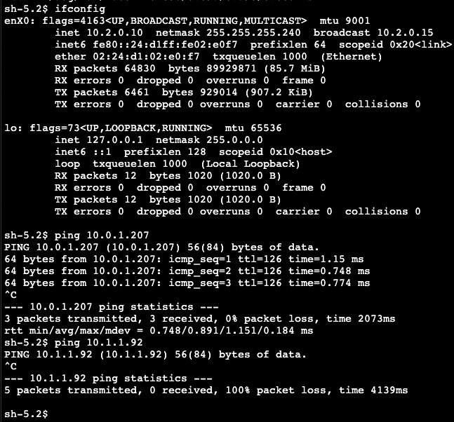
As you can see we have the following flows:
1- HUB to Spokes - 100% success - which is what we want**.**
2- Spokes to HUB - 100% success - which is what we want**.**
3- Spokes to Spokes - 100% failure -which is what we want.
If you make it all the way to here, thank you and congratulations! you have successfully segmented your H&S topology on AWS using AWS Transit Gateway.
7. Security & Monitoring:
- Use Network ACLs, Security Groups, and AWS Network Firewall.
- In the test above I have created an Allow Rule on the Security Groups for ICMP traffic to allow traffic from 10.0.0.0/8 (summarisation of VPC CIDR) .
- You can also Monitor with AWS CloudWatch and VPC Flow Logs.
8. Cleanup:
- Please remember to delete the resources you deployed to avoid unwanted costs.
Conclusion
And there you have it! If setting up network segmentation with AWS Transit Gateway were a theatrical play, we’d have just delivered a Tony Award-winning performance! But jokes aside, we’ve just navigated the intricate world of hub-and-spoke architectures, ensuring that our VPCs play nice in their respective sandboxes, all while keeping unwanted traffic at bay. Remember, in the ever-evolving realm of cloud networking, it’s not just about keeping the lights on; it’s about orchestrating a symphony of packets, routes, and CIDR blocks. So, give yourself a pat on the back, and maybe even a chuckle, because you’ve just mastered one of the core pillars of AWS networking. Now, go forth and segment!